- Markets
- Catalogue
- Services
- Tools & Resources
- Downloads
- About Indeco
- Newsroom
-
Nexans Insights
- Nexans Insights
-
Blog Posts
- Overview
- Growing demand for copper and its future
- Electromobility: the road to building an increasingly sustainable transport system
- Guide to Prevent Fires and Accidents at Home (only in Spanish)
- Ten technologies to electrify the future: Electrical and Fire Safety
- Big data & AI
- IoT
- Unveiling innovations transforming the industry
- Transforming buildings industry with 3D printing and modular construction
- The path to effective fire safety in buildings
- Powering the digital change
- Unleashing the power of DC buildings
- Sustainable buildings for a brighter future
- Industry 1, 2, 3, 4... and 5.0
- Nexans copper odyssey
- Limitations of aluminium as an electrical conductor in residential installations
- Solar PV cables for the solar farms of the future
- Find Distributors
- Search
- Contact us
- Compare
- Sign in

The invisible infrastructure of solar energy
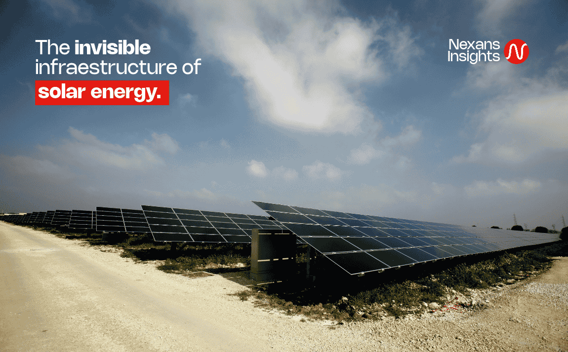
DC cabling carries power from the PV modules to the inverters.
The invisible infrastructure of solar energy
During periods of high solar irradiance, an insulation fault can trigger a solar farm’s electrical protection systems and take part of the plant offline. Even with sunlight still reaching the panels, the affected section stops delivering power. The fault may originate in a cable run that is barely visible beneath the panels or in a section routed through a conduit to an inverter.
According to an estimate in the Nexans whitepaper, photovoltaic (PV) cabling can account for between 1% and 2% of a solar farm’s upfront capital expenditure (CAPEX). In a plant designed to operate for 25 to 30 years, the performance of that infrastructure affects safety, plant availability, and the cost of generating electricity. Three decisions made during project development can help manage that impact.
What changes as solar farms grow?
Solar development in Latin America includes projects rated in the hundreds of megawatts, some with integrated battery energy storage systems. At that scale, cables and wiring harnesses connect the modules and carry direct-current (DC) power to the inverters. Once the inverters convert DC to alternating current (AC), power travels through the site’s electrical network to the grid connection point. The circuits and equipment along that route form part of the electrical balance of plant.
Changes in module and mounting technology place different demands on those circuits. Depending on the system design, a 1,500 V DC architecture can accommodate longer strings of modules connected in series, reducing the number of parallel circuits needed. Some high-power modules operate at higher currents, which affects the conductor’s required current-carrying capacity. At sites with solar trackers, the cable sections that move with the structure flex repeatedly as the panels follow the sun.
1. Evaluate cabling costs over the life of the solar farm
The price per meter is a straightforward way to compare supply bids. To see how the choice of cable can affect operating costs, consider a long DC cable run. The conductor’s cross-sectional area affects its electrical resistance and, in turn, how much energy the circuit loses. The cable jacket and insulation serve a different purpose. How well they suit the conditions on site influences how long the cable can remain in service before that section needs repair or replacement.
Total cost of ownership (TCO) combines the costs of purchase and installation with the costs that arise over the plant’s operating life, including electrical losses, maintenance, and downtime. An unplanned intervention involves locating the fault, sending out a crew, and repairing the affected cable run. For as long as the section remains offline, the plant loses the electricity that section would have generated. Safety is part of the same assessment. A faulty connection can cause electrical arcing and increase the risk of fire.
This assessment connects cabling choices to the levelized cost of energy (LCOE), the average cost per unit of electricity generated over the life of the plant. One option may require a higher upfront investment and lead to lower electrical losses once the plant is operating. A life-cycle analysis helps estimate whether those savings justify the additional investment under the project’s operating conditions.
2. Plan installation to protect the cables and the crew
A cable can be damaged before a solar farm generates its first kilowatt-hour. During construction, crews move reels, cut cables to length, and route them into position. Dragging a cable across rough ground or pulling it with too much force can damage its jacket during installation. In some cases, that damage becomes apparent only when the plant enters service and an insulation fault occurs.
Cable guide rollers limit contact with the ground and reduce friction during pulling. A mobile workstation helps crews move the cable and prepare it close to where it will be installed. Preconnectorized cable assemblies shift some of the connection work to the factory and can simplify assembly in the field.
Repeatedly handling materials or working with arms raised can cause fatigue over the course of a shift. Innovative Solutions like the Nexans Solar Kit, including protective shoulder pads and assistive exoskeletons. Their usefulness depends on how well they suit the crew’s tasks and how they fit into the installation sequence.
When planning the work, the construction team can decide where to prepare the cable, how to get the reels to each work area, and which tools crews will need to pull the cable into place. Coordinating these decisions with engineering helps identify cable routes that would be difficult to install and connections that would be easier to prepare in the factory.
3. Bring in an electrical specialist during early design
During front-end engineering design (FEED), the team can review the electrical architecture while there is still time to adjust cable routes, conduits, and installation methods. Bringing in an electrical specialist at this stage helps the team account for the thermal, mechanical, and insulation requirements of each cable run in the project specifications.
In Chile’s Atacama Desert, exposure to ultraviolet (UV) radiation and wide differences between daytime and nighttime temperatures influence the choice of cable jacket and how the cables are routed. Materials expand and contract as temperatures rise and fall. If the route transfers the resulting mechanical stress to the connection points, that movement can strain connectors or terminals.
At high-altitude sites in the Peruvian Andes, lower air density can make it harder for exposed conductors to dissipate heat. That affects how engineers assess their thermal performance. At coastal sites in Peru, salt exposure also calls for protection against corrosion at joints and terminals. Two projects in the same country can call for different cable specifications.
In tropical areas of Colombia, humidity and water that can collect in trenches or conduits affect the conditions cables face in service. Identifying where the cables could be exposed to water helps the team choose suitable cables for each run and coordinate routing with the rest of the construction work.
Addressing these differences during design lets the team compare bids against the conditions the plant will face in operation. Component durability also matters to the project’s sustainability objectives. Replacing components before the end of their expected service life uses more materials and requires additional work on site.
From design to operation
The operations team inherits decisions made during design, procurement, and construction. Documenting the operating conditions and the criteria used to select the cables gives maintenance crews a record they can use years later. They can see why a particular cable was chosen for a specific route and what requirements a replacement would need to meet. That record supports future inspections and repairs along the electrical path from the modules to the grid.
Reference document
The Invisible Infrastructure of Solar Energy: Safety, Efficiency, and Service Life of Photovoltaic Projects in Latin America (PDF)
Our websites
Select your country to find our products and solutions
-
Africa
- Africa
- Ghana
- Ivory Coast
- Morocco
- North West Africa
- Americas
- Asia
- Europe
- Oceania